Prototype Results
The results of first semester.
Design Overview
The plan
The AMP team will produce a learning mechanism to teach children how to drive an electric wheelchair. We will use Arduino because it's easy to learn and could reach all our demands also it's open source project and it's easily to connects to the computer, USB. The source code is already available, so there are a lot of source code and that will make us easy to use it. The code could be easily uploaded through a USB cable. The reason of using sensors in our prototype will be to detect when the powered wheelchair is too close wall. This could possibly be used to steer the driver away from the wall, with varying levels of assistance for the user. Laser sensors will work same the sonar sensors, yet utilize light set up of sound. Methods of data logging and microprocessors will need to be used, this purpose will be to track a student’s progress as well as communication between motors, sensors, and inputs.
The current microprocessor that the team will use is a type of Arduino and the data collection will use with XBee and Processing. We will have two head switches, a force feedback joystick, two to three switches, and an emergency stop switch to be the input. The joysticks will allow the children to control the chair movement. The force feedback joystick is for child to learn and adapt to new type of inputs. In addition, we will use head switches because the children are likely accustomed. Also head switches make the child's controlled movement in the mainly with head, so the left one is rotation of the chair and the right one is to move straight forward. The switches are for Krista to change the mode. And she could twist and push down the emergency stop switch in urgent circumstances.
Sensors
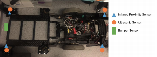
The purpose of using sensors in our prototype will be to detect when the project wheelchair is too close to an obstacle. This could possibly be used to steer the driver away, with varying levels of assistance for the user. There are three different types of sensors that we are currently interested in; each has their own specific pros and cons.
Infrared proximity sensors work by sending out a beam of infrared light and detects changes in the heat of the return signal. The cooler the return signal, the farther away the walls or other objects are. However, a downside to this sensor is that if you are near a particularly hot or cold wall then it could be detected as further away or closer to you than is accurate. An upside to this sensor is that infrared sensors do not interfere with one another, as it detects the change in signal. This is unique amongst the other sensor models in consideration.
Sonar sensors operate by sending out sound waves at high, inaudible frequencies and measuring the amount of time it takes to get a return signal. Sound moves at a uniform speed, so the measurement would be fairly precise, unless a signal was sent out before the signal of another returned. Both sensors would detect the first return signal, and would calculate different times of return, thus measuring the same wall at different distances.
A bumper sensor can be utilized if an object is short and is not detected by the other sensors. This can also be what the data logger mainly tracks. When the bumper is pressed, an object has interfered with the mobility of the student. The amount of times that the bumper is pressed will show if the student’s driving has improved after a continued use of time. The bumper will be attached to the front.
Inputs
The device will have these inputs: two head switches, force feedback joystick, and a joystick. We will also imput two to three on/off switches, and one emergency stop switch.
Head switches are what the children are likely accustomed to and are familiar with. The force feedback joystick will be for the child to learn and adapt to a new type of input. The joystick is what is commonly on battery powered chairs and will be the end goal for the student to accomplish utilizing. Each of the inputs will allow the children to control the chair’s movement. Head switches are for when the child’s controlled movement is mainly with their head. The proposed use for these is to have two head switches – the left one is for rotation of the chair and the right one is to move straight forward. A third one is also a possibility to allow rotation in the opposite direction since the base with the ramp is fairly long.
The force feedback joystick is a physical device that converts the movement of a plastic rod into electronic information that the microprocessor can handle. The main goal of this input is to be a training mechanism for the students to driving an electric chair with a joystick type device.The force feedback joystick is developed to avoid dangerous situations and can offer resistance based on the sensors input. The joystick could offer resistance to discourage a certain route as well as assistance for avoiding obstacles.
The joystick, which is more commonly used, is built into the base currently. A similar input device will likely be on the chair that the child receives when fitted with a permanent power assisted chair.
We plan to put two or three for the four modes: headswitch mode, joystick mode, assistance force feedback joystick, and the minimal assistance force feedback joystick. With the witches on or off, the mode with be changed. For safety,an emergency stop switch would be added on the chair. All of the inputs will work independently from each other, and only one method will be in use depending on the mode that is selected.
Data logging
Methods of data logging and microprocessors will need to be used. This purpose will be to track a student’s progress as well as communication between motors, sensors, and inputs. The current microprocessor that the team is using is Arduino and the data collection will use with XBee and Processing.
XBee is a data logger that we will use for our project. The Digi International XBee family is a series of modular products that are capable of wireless signal transporting. The XBee family has many different modules to choose from. XBee is on the lower end of cost in terms of other methods that could be used. The XBee Explorer USB Dongle connects directly to a USB port on the computer. This option is ideal and easy for the client. The goal is that the data logger never has to be removed from the device.
Processing is a programming language that we would use with XBee and the data that it collects. Since the program is open source and readily available, the team will have access to various libraries that utilize XBee and Arduino. It is suitable as an introduction programming language. The Processing language can control the XBee module. It can connect easily and return clear feedback. The language has a simplified syntax and a graphics user interface. A graphical user interface will be available on the PC as a desktop application to handle all the required tasks at hand in a user friendly way. Controls of the mobility unit would be easy be set and data would be easy to manipulate.
Prototype Results
DC motor
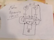
The aim of this part of the prototype was to integrate a DC motor with a transistor network and an Arduino to reach the end goal of getting a motor to start or reverse based upon the input of the user. The transistor network works by allowing the current to flow through the motor if A0 or A1 are different signals. Its direction depends upon the output signals of A0 and A1. If A0 is on and A1 is off, then the transistor connected to ground and the negative lead of the motor will allow current to flow out of the motor, and the transistor connected to power and the positive lead of the motor will allow current to flow into the motor. If A1 is on and A0 is off, then the transistors A0 had on before will be off and the other two will be on (the negative lead of the motor will be connected to power and the positive will be connected to ground due to a similar process as the one described previously). If A0 and A1 are on, then the motor will not move, but there will be a short-circuit (which, in hindsight, is a terrible idea). However, this is not a major problem as A1 and A0 will never be on simultaneously; if the motor is not meant to move then both will be off, which will not turn on any transistors whatsoever.
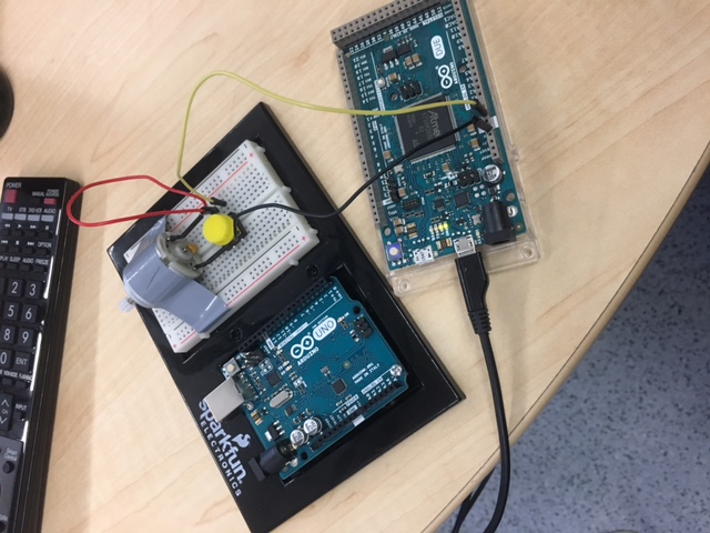
The plan’s shortcoming was found in this little piece of code that is attached here. Though it is supposed to wait for a user’s input (if there is no user input then Serial.available() would render a 0 value), the program bypasses this segment of the code entirely. Thus, I have no idea how to get past this roadblock. The alternative to this plan was that I attached the DC motor to ground on the negative lead, the positive lead to one end of a button, and the other end of the button to power. Pushing down on the button would move the motor and therefore the motor turning on and off was determined by user input, but the direction was not. However, reversing the location of the positive and negative leads would cause the motor to spin in the opposite direction.
Joystick prototyping
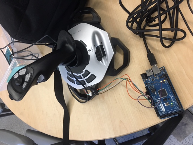
We utilized two joysticks for this aspect. The top one pictured was intended to have force feedback. It did not, and a new joystick will be ordered soon. The code will add onto what we have currently. The joystick currently outputs the direction on the x and y axis. We bypassed the USB port and detached the wires to input onto the Arduino board. At the beginning of each use, the joystick will calibrate at the joysticks current position to decide where the movement is vs idle placement. It is exetremely sensitive and accurate. The code itself consists of two loops.
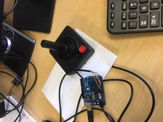
The second joystick works differently in the sense that each direction is recorded as an input with five directions available.
Sensors
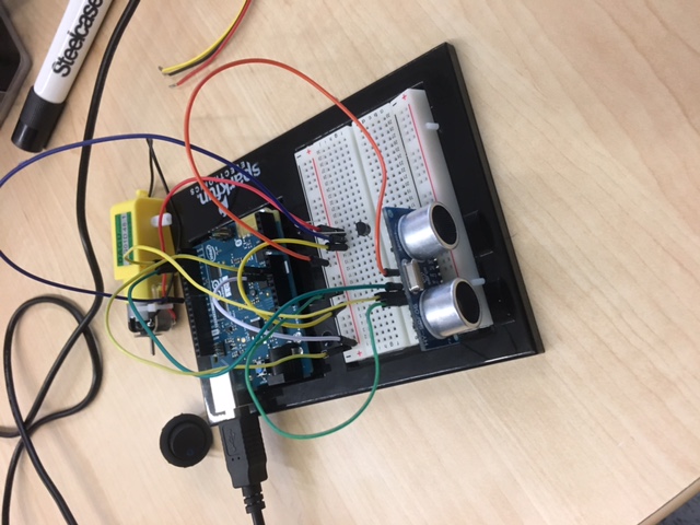
Both the infrared and sonar sensors were tested. They proved to be a bit finnicky. Once they are working, they are reliable to the centimeter. In future implementation, we would like to use four of each with placement onto the device. They also worked on separate code and we will need to bring everything together for the final project. We were definitely happy to see its accuracy in two devices that were inexpensive.
Photos
